Mark's blog
Probably techy. Certainly useless.
about
- - mark@mfinn.net
- github.com/markfinn
- twitter.com/mfinn
Railroad Light 1
A few years ago I bought an old railroad signal light at a swap meet. I though it would be fun to convert it into an RGB indicator or some kind of multi-color stop light for my kids to play with outside while riding their bikes.
I don’t have the electronics done, but the results so far show some promise:
(Annoyingly, I can’t get the video tag to work here on github, even though it works locally. movie is at the bottom of the page for now)
The Light
The original light was a little broken, but for $10, I can’t complain. Once I’m done, I might replace the circle of black plastic since it’s cracked, but I might just be able to glue and screw it to get it to keep the right shape. 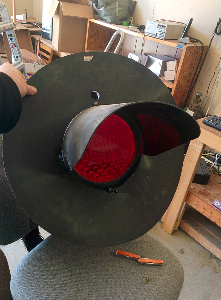
Dissassembly
The light is a fairly servicable device. The front swings open, and everything can be disassembled and repaired or replaced. This one had a broken side window, so a bird had crawled in at some point. I’ll stick a circle of some cheap plastic in there when I close it up to keep water and future birds out. The original light is a 10V bulb that is mounted at the focal point of a parabolic mirror. The focus is even adjustable, which I will make use of. 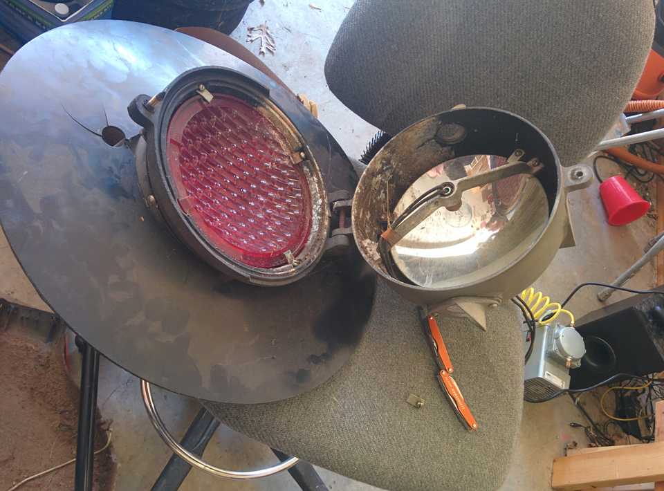
I was able to find an 8” clear glass lens to replace the red plastic original. I got it on Amazon, and it’s meant for an underwater pool light housing. Other than the faint “do not light unless submerged” and the fact that it is clear glass, it is pretty close to a copy of the original.
At this stage I also removed the side windows for fixing, cleaned the mirror, and ran new wiring out the back. 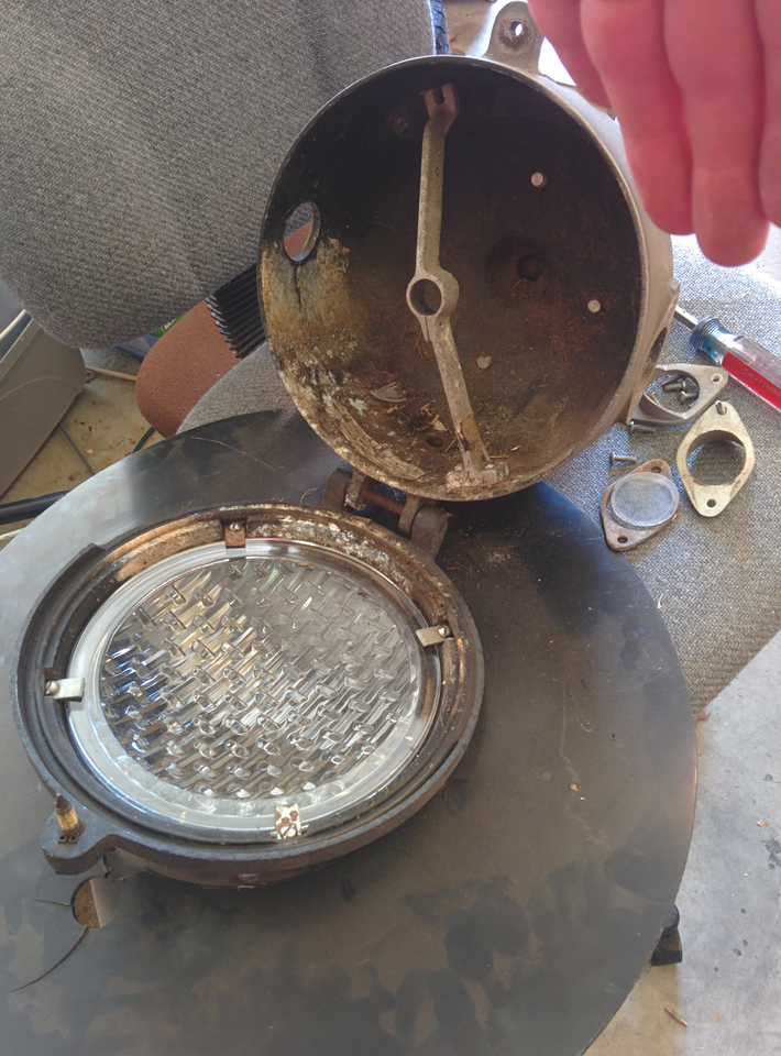
I decided to use a BlinkM MaxM as as simple way to get an RGB LED in there.
I haven’t done the code yet for my final setup, and the BlinkM is just running its demo program at the moment.
The Mount
The mount on github fits in the original bulb socket holder, and allows some focus control. I made a conduit in the center for the wires, but as you can see in the following pictures, I forgot to thread the wires through. I made the mount on my reprap, and it was the first thing that I’ve managed to print since last fall since it’s been cold out by the printer. The mount is held on by double sided tape. I wanted to make little latching fingers that the BlinkM would snap into, but that would have taken me much longer than the 5 minutes this simple mount did in OpenSCAD, so I went with simple and fast. 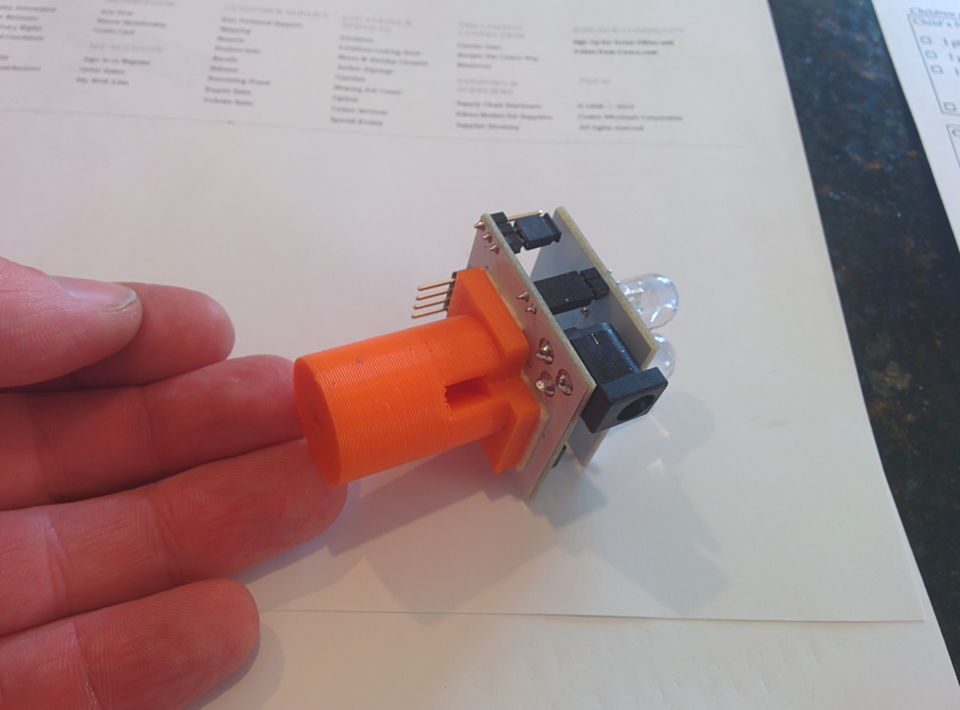
Here’s the mount and LED board in place. I wasn’t very careful about focus other than lining the LED domes up with where the filament used to be. I figure I’d adjust it once I saw it in action, but it turned out to be close enough.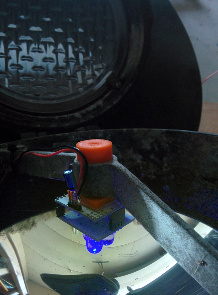
Troubles
I had a few issues at at this stage.
First, the BlinkM was dim. I found that the voltage was stuck at around 3.7v at the board top board. It turned out that I was using the barrel plug power input with the 5V 2A power supply I had bought for this project. It turns out after reading the schematic that the barrel plug goes through a 7805 lin-reg before becoming VCC on the board. Any variant on a 7805 is porbably not going to be a low-dropout regulator, and this was no exception. I switched to applying power directly to the arduio VCC connector, and this were better.
At the same time that I switched to the non regulated input, I added the longer wire (6 feet of 22 or 24 guage, I didn’t really look) and found that the BlinkM wouldn’t turn on, it would just flash a little. I assumed that the LEDs switching on were causing enough voltage drop to reset the ATTiny. Since I had added Wire AND cut out any input capacitance at the same time, I don’t really know which caused it, but either way, it was a problem now. My son had just found a 16V 33uF electrolytic cap on the floor, and he hadn’t crushed it too badly when he “found” it, so I decided it was just the right size that I guess I needed. Adding the cap directly to the BlinkM’s input pins solved the problem.
Lastly, I had an issue of getting good color blending. The parabolic reflector in the signal body is meant to tale a point source of light, like a single bulb with a small fillament, and turn that into a large ray out the front lens. Replacing the single bulb with three LEDs that were sepoarated by nearly a centimeter center to center left me with three separate beams that didn’t really mix well. When the LEDs were all on, instead of getting a whilte light, I could see a psychadelic red-green-blue mosaic that really wasn’t what I was going for. So far, I’ve improved this by tie-wrapping a translucent piece of plastic (a chunk from a Radio Shack bag) over the LED assembly with a bit of “poof” in the plastic where it passes in front of the LEDs. This helps quite a bit, although it doesn’t completely solve it.
Next
This gave me what you see in the video at the top of the page. Next Up: a wall mount, plus software and controls. I’m thinking about USB to the near by router for computer control, plus either an optical encoder or wireless remote for playing. I’m considering those two option since they are what I have the parts for on my desk right now.
blog comments powered by Disqus